


DOMETIC CIRCUIT BOARD DDC 115 / 230V 4220002 / ASY-405-XXX / 290000201
Follow these instructions to connect and set the programmable parameters of the DDC circuit board(s).
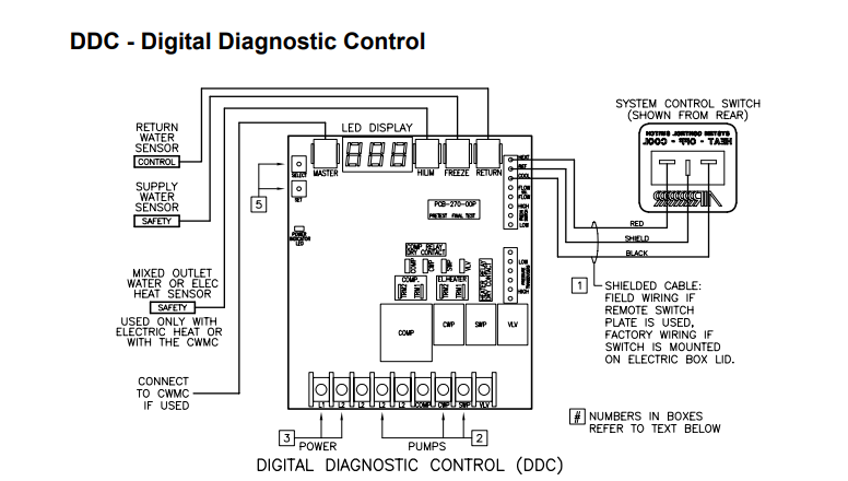
All wires connected to DDC terminal block should have captive fork or ring type terminal connections.
1. With main circuit breaker off, connect the System Control Switch wires to the circuit board as
shown in the above diagram (if the switch is located on the electric box then it is already wired).
2. Connect pump or Pump Relay Panel (PRP) wires. Wires connected to pumps should be tightly
crimped and insulated with “heat shrink” wire wrap. Pumps larger than 3/4HP (559 watts) require a
dedicated PRP. Each PRP should have its own circuit breaker sized for the pump, but not to exceed
20 amps.
3. Connect main power supply from a dedicated circuit breaker; see unit data plate for electrical
specifications.
4. With the System Control Switch turned OFF, turn on the chiller’s circuit breaker. The DDC circuit
board will briefly flash its software revision (e.g. “A32”) on its LED display, and then it will go
blank.
5. All critical DDC programmable parameters are preset at the factory. These parameters can be
viewed by pressing the SELECT button and can then modified by pressing the SET button. If you
wish to change any of them, only do so while the System Control Switch from the OFF position.
Please refer to the DDC Programmable Parameters section below for complete information and
instructions on how to modify each programmable parameter.
VERY IMPORTANT: Proper setting of all the DDC Circuit Board programmable parameters must be
completed and verified before starting the system! Please see the DDC Programmable Parameters
section below for details on how to check and set the DDC programmable parameters. See also the
DDC Operations Manual (L-2281) for more detailed information.


