


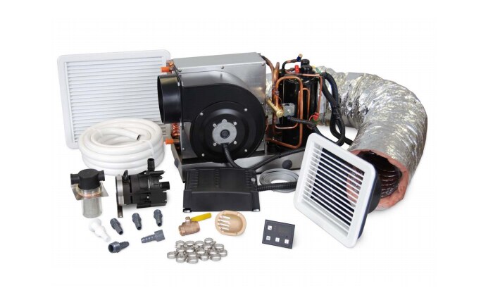
Dometic™ installation kit:
This kit was purposely designed to work with a 10,000 BTU self-contained marine air conditioner. It includes all the plumbing and distribution parts that complete the system for a new installation.
Features:
- Includes all components required for a standard installation.
- Space-saving design allows the kit to be used in small or compact areas.
- Designed to be used with ECD10K AC unit.
Kit includes:
|
1 |
|
1 |
|
1 |
|
1 |
|
1 |
|
1 |
|
1 |
|
1 |
|
10 |
|
1 |
|
1 |
|
1 |
|
1 |
|
1 |
| Duct Ins Flex 6" |
Installation Tips:
AIR CONDITIONER UNIT MOUNTING
• Do not install in engine room or bilge areas, must be sealed away from exhaust or fumes.
• Keep proper spacing allowed around unit.
• Must be attached to solid, level platform with four hold-down clips provided.
• The condensate drain line should be routed aft and down hill to a sealed sump (not bilge), and should have a trap.
GRILLES AND DUCTING
• Supply-air grille should be mounted as high as possible.
• Return-air grille should be mounted as low and as close to the unit as possible.
• Return-air grille should mounted away from exhaust and bilge vapors.
• Ducting should be pulled taut, straight and properly connected with no excess.
ELECTRICAL
• If pump wires need to be extended by butt connections, make sure they are tightly crimped and heat shrunk.
• AC power source installed and grounded/bonded in accordance with ABYC standards.
• Connect control wires to terminal strip with ring terminals
SEAWATER COOLING SYSTEM
• Speed scoop located as far below the water line and as close to the keel as possible, with the scoop’s strainer facing
the bow. (See section C of Figure 1: Kit Installation Diagram, page 5.)
• Shut-off valve and speed scoop properly sealed and tight.
• Seawater pump at least one foot (305mm) below water line and securely mounted.
• Strainer mounted below pump with access to filter.
• Double/reversed stainless steel hose clamps on all hose connections.
• Threaded-seal tape on all threaded connections.
• Hose runs uphill from speed scoop to strainer, pump and air conditioning unit.
• Water flowing freely and steadily from overboard discharge while pump is running.


 - 218000117")
 - 218000117")

